TL;DR
Precision metal stamping holds tolerances as tight as ±0.005 mm on specific features by combining carbide tooling, servo presses, controlled die clearance (typically 5–10% of material thickness), tight coil specs, and in-die sensing. Not every feature can hold the same number, though. Feature geometry and datum choice decide the limit, and most of the arguments I have with design engineers start right there.
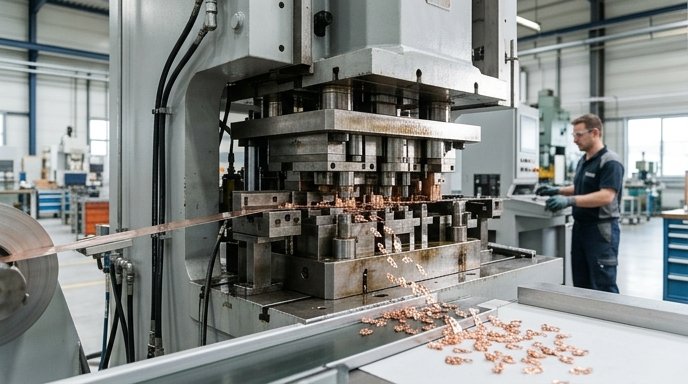
What “Tight Tolerance” Actually Means in Stamping (Feature by Feature)
Precision stamping tolerance depends on the feature. A pierced hole diameter can hold ±0.01 mm. A bend angle rarely holds tighter than ±0.5 degrees without secondary operations. Engineers often apply a blanket ±0.05 mm tolerance across an entire part, which forces stampers to over-engineer the die or walk away from the quote.
Different physical mechanics govern different features. Piercing a hole is a direct shearing action, which is why it’s so repeatable. Bending metal introduces springback, and springback depends on yield strength and grain direction, neither of which the stamper fully controls. DIN 6930-2 provides baseline tolerances for stamped parts, but precision shops routinely beat those baselines by a wide margin.
| Feature Type | Standard Tolerance | Ultra-Precision Limit | Primary Limiting Factor |
|---|---|---|---|
| Hole Diameter | ±0.05 mm | ±0.005 mm | Punch wear, die clearance |
| Hole-to-Hole Position | ±0.10 mm | ±0.02 mm | Strip progression accuracy |
| Edge-to-Hole | ±0.15 mm | ±0.05 mm | Feed release, pilot pin fit |
| Bend Angle | ±1.0° | ±0.5° | Springback, material hardness |
| Flatness | 0.1 mm / 25 mm | 0.05 mm / 25 mm | Internal material stress |
| Burr Height | 10% of thickness | 5% of thickness | Tool sharpness, clearance |
Die Clearance — The Single Biggest Lever on Edge Quality
Die clearance is the gap between punch and die, expressed as a percentage of material thickness. For precision stamping of mild steel, that number usually sits in the 5–8% per side range. This single ratio controls burr height, edge straightness, and dimensional repeatability more than any other variable in the process.
When clearance is too tight (under 5%), the material undergoes secondary shearing. You get a nice burnished, straight edge, but friction goes through the roof. The punch wears faster, and the extreme pressure can snap the punch outright. I’ve watched a new engineer spec sub-4% clearance on a 2 mm cold-rolled part and lose three punches in a shift before anyone caught it. When clearance goes the other way (over 12% on mild steel), the material bends before it shears. The result is a big edge rollover and a burr that blows past 10% of the thickness.
Different materials want different clearance percentages. Stainless (304 or 316) wants 9–11% because of its shear strength and work-hardening behavior. Soft aluminum wants tighter clearances, usually 4–6%, so the material doesn’t extrude into the die matrix instead of shearing cleanly. Copper alloys sit somewhere in between, closer to the mild steel numbers in my experience, though the exact value depends on temper.
Tooling — Why Carbide Dies Are the Price of Admission
Holding ±0.01 mm over a real production run requires tooling that doesn’t wear down after a few thousand strokes. Standard D2 or M2 tool steel punches typically need regrinding every 250,000 to 500,000 strokes. As the tool wears, clearance opens up, burr height climbs, and hole diameters start to shrink. Then the parts drift out of spec and someone has to decide whether to pull the die or run until the SPC chart screams.
Precision stampers use tungsten carbide inserts in the high-wear positions. Carbide grades with 10–15% cobalt binder can run 2 to 5 million strokes between sharpenings. The hardness locks the clearance in place and kills the dimensional drift that eats tool steel dies alive.
Carbide costs more up front, and the die set has to be rigid or the brittle inserts will shatter. That’s why most precision shops run modular die designs. You swap a worn carbide insert in the press without pulling the whole tool, and the Cpk stays flat across millions of hits. Downtime is where margin goes to die.
Press Choice — Why Servo Presses Changed the Tolerance Game
Mechanical presses run on a fixed flywheel and crankshaft. Ram speed is constant, and you can’t change it mid-stroke. Servo presses replace the flywheel with high-torque servomotors, so you can program velocity and position at any point in the stroke.
That programmable motion translates directly into tolerance. Slow the ram down just before it hits the material and you reduce impact shock, which cuts tool deflection. At bottom dead center you can dwell, holding pressure on the part for a fraction of a second so the material yields completely and springback variation drops. Modern servo presses like the AIDA DSF series hold shut height repeatability within ±0.01 mm. That consistency means coining and forming stations hit the exact same depth every stroke, which takes a major variable out of your bend angle and flatness budget.
The downside, which nobody in a sales pitch mentions, is that servo presses cost two to three times what an equivalent mechanical costs, and the maintenance guys have to learn a whole new control system.
The Coil Nobody Looks At — Material Variables That Blow Tolerance Budgets
A perfect die in a perfect press will still produce out-of-tolerance parts if the incoming coil varies. Standard steel thickness tolerances come from ASTM A568. A standard 1.5 mm coil can vary by ±0.08 mm. If you’re trying to hold a ±0.05 mm form tolerance, the raw material alone has already eaten your entire budget before the strip even hits the first station.
Precision stamping means ordering “restricted tolerance” or half-standard coils, and paying for the privilege. Beyond thickness, hardness variation lot to lot changes how the metal shears and bends. Coil camber (the slight curve in the strip as it unwinds) can walk the material off-center as it feeds through the progressive die, which quietly destroys hole-to-edge tolerances before anyone figures out why the first-off is good and the hundredth-off isn’t.
Grain direction matters too. Sheet metal has a directional grain from the rolling process. Bending parallel to the rolling direction raises the cracking risk and makes springback unpredictable. The strip layout has to put bends transverse to the grain, which sometimes fights with the most material-efficient nesting. That trade-off is one of the first things I look at when a part keeps failing bend-angle checks for no obvious reason.
In-Die Sensing and Closed-Loop SPC — The Real “Precision” Differentiator
Ultra-precision shops don’t wait for a part to reach the quality lab. They monitor the process every stroke. Systems like the Wintriss SmartPAC use tonnage monitors to measure the force applied during the cycle. A tonnage spike means a dull punch or a thick section of coil. A drop means a missing feature or thin material. Either way, you know within one hit.
Sensors inside the die protect the tooling and the tolerance. Proximity sensors and optical lasers verify that the strip has fed to the exact required pitch, usually within 0.02 mm, before the press is allowed to cycle. If the feed is short, the press stops in milliseconds, which is the difference between a crash that scraps a die and a crash that scraps a part.
This data feeds into SPC software. Instead of pulling one part every 1,000 strokes to a CMM, the press monitors strain and feed data continuously, and operators adjust shut height or swap a punch before the parts drift out of Cpk.
Springback, Coining, and the Tricks for Hitting Bend-Angle Tolerance
Bend tolerance is where most stamping jobs fail. When metal bends, elastic recovery pulls it back toward flat the moment the die opens. Anything tighter than ±1 degree on a standard 90-degree bend almost always needs a secondary trick.
Stampers use two main methods to defeat springback. The first is overbending, where the die bends to 92 degrees so the part relaxes back to 90. The second, more precise method is coining. A sharp punch compresses the material right at the inside radius, pushing the yield stress through the entire thickness and permanently setting the angle. Done right, coining gets you to ±0.25 degrees.
Before anyone cuts steel, tooling engineers run FEA in AutoForm or PAM-STAMP. The software simulates the forming, predicts springback based on the material card, and alters the die CAD geometry to compensate. The honest answer is that the simulation is only as good as the material data you feed it, and if your supplier can’t give you accurate n-value and r-value numbers, the compensation is a guess dressed up in color plots. I still default to AutoForm for anything with a complex bend sequence, even though for simple two-bend brackets it’s overkill. Old habit from a shop that got burned on a dashboard bracket in 2011.
How Drawing Choices Can Make a Tolerance Impossible to Hit
Engineers often make stamped parts impossible by applying machining GD&T rules to sheet metal. The most common sin is calling out a formed edge as a primary datum. Formed edges move around because of thickness variation and springback. You cannot build a repeatable inspection fixture off something that isn’t repeatable in the first place.
For tight tolerances, locate from blanked features. Pierced holes should be Datum A and B. All pierced holes in a given station are cut simultaneously by the same die block, so their relationship to each other is fixed by the steel. That’s a free gift the process gives you, and it’s shocking how often prints throw it away.
Overlapping tolerance zones kill parts too. A tight profile tolerance on an entire bent bracket, combined with a tight true position on a hole on the bent flange, creates a stack-up that fights itself. Composite position tolerances let the hole pattern float slightly relative to the bend while keeping the critical hole-to-hole distance tight.
The Cost-Tolerance Curve — When Tighter Stops Being Worth It
Tightening a tolerance from ±0.1 mm to ±0.02 mm doesn’t nudge the price up. It can double it. The cost-tolerance curve in stamping is exponential, not linear. Hitting ±0.02 mm means carbide tooling, restricted-tolerance coil, and slower press speeds to manage heat and vibration.
Anecdotally, doubling tolerance precision tends to push per-part cost up somewhere in the 40–60% range once secondary operations enter the picture, though the exact number depends heavily on volume and material. If a part requires a 100% sheared edge with zero die break, conventional stamping can’t do it at all. You have to switch to fine blanking.
Fine blanking uses an impingement ring to clamp the material and a die clearance of about 0.5% of thickness. The result is a smooth, extruded edge and tolerances around ±0.01 mm. The catch is cycle time. Fine blanking presses run 30–60 strokes per minute versus 200–500 for conventional precision stamping, and the piece price reflects it. At low volume with extreme tolerances, CNC machining frequently comes in cheaper than amortizing a fine blanking die. I’ve seen quotes go that way more than once, usually to the surprise of the buyer.
FAQ
What is the tightest tolerance achievable in metal stamping?
On specific features like pierced hole diameters, precision stamping can hold ±0.005 mm with carbide tooling and strict material controls. Bend angles and formed features generally cap out around ±0.25 degrees.
Is fine blanking the same as precision stamping?
No. Conventional precision stamping shears the metal, which leaves a clean cut band and a rough fracture zone on the edge. Fine blanking uses extreme clamping pressure, a V-ring, and near-zero die clearance to effectively extrude the metal through the die, which leaves a 100% smooth sheared edge. It’s a different process category, not a tighter version of the same thing.
How does die wear change tolerance over a production run?
As punches and dies wear, clearance opens up. Hole diameters shrink, burrs grow, edges get worse.
When should I use precision stamping instead of CNC machining?
Stamping tends to make sense above roughly 50,000 parts per year. The progressive die costs a lot up front, but the piece price can drop to pennies. CNC has low setup cost and a stubbornly high piece price that doesn’t improve with volume.
What Cpk should I expect from a precision stamping supplier?
For standard precision features, 1.33 is the baseline. Critical automotive or medical work can hold 1.67, assuming the drawing tolerances are realistic for sheet metal in the first place.