TL;DR: Metal stamping is a cold-forming process that uses a press and dies to shape flat sheet metal into finished parts through operations like blanking, piercing, bending, and drawing. High upfront tooling costs, extremely low per-part costs once you clear roughly 5,000 units. Common materials are cold-rolled steel, stainless, and aluminum. Don’t stamp prototypes, sub-500-unit runs, or parts with complex 3D geometry that really want multi-axis machining.
How a Stamping Press Actually Turns Flat Metal Into a Part
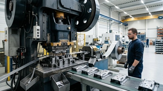
A stamping press converts flat sheet metal into a finished component through a highly repeatable mechanical cycle. Three main pieces do the work: the press (force), the die set (shape), and the feed system (material in).
During a standard cycle, a servo-driven feeder pushes a specific length of coiled sheet metal into the open die. The ram descends, closing the die. The upper tool (punch) forces the material into or through the lower tool (die block), executing the cutting or forming operations. As the ram returns to top-dead-center, a stripper plate pulls the material off the punch. The finished part ejects via air blast or gravity, and the feed advances the strip for the next stroke.
Cycle speeds vary heavily based on press tonnage and part size. Heavy-duty servo presses, such as the AIDA DSF-N2 series (rated for 2,000 to 3,000 kN of force), typically operate between 30 and 85 strokes per minute. Light-tonnage, high-speed mechanical presses used for electronic contacts, like the Bruderer BSTA 280-75B, can reach up to 2,500 SPM. Different machines, different worlds.
The Core Stamping Operations, Ranked by Frequency of Use
The core operations are blanking, piercing, bending, drawing, coining, embossing, flanging, and trimming. Most stamped parts need some combination of these to get to final geometry.
Blanking and Piercing: Blanking cuts the rough perimeter of the part out of the main strip. Piercing punches holes or internal shapes out of the part. Both are shearing operations that require punch-to-die clearances typically ranging from 5% to 12% of the material thickness.
Bending and Flanging: Bending deforms the metal along a straight axis. Flanging creates a bend along a curved axis. Both apply tension to the outer radius and compression to the inner radius, which is why you need proper bend allowances to calculate your flat pattern.
Drawing: Drawing pulls the metal into a die cavity to create deep, cup-like shapes (battery enclosures, beverage cans, that sort of thing). If the depth exceeds the diameter, it’s classified as deep drawing.
Coining and Embossing: Coining applies extreme pressure to plastically deform the surface of the metal, altering thickness to create fine features or tight tolerances. Expect to spec 3 to 5 times the tonnage you’d use for blanking the same part. Embossing creates raised or sunken designs without changing the overall material thickness.
Progressive, Transfer, and Compound Dies — Which One Fits Your Part
Progressive dies perform multiple operations as the strip advances between stations. Transfer dies move the part mechanically between separate die stations. Compound dies perform multiple operations in a single press stroke. Which one you pick depends on part size, feature count, and annual volume. That’s it. Everything else is a detail.
Progressive Dies: The standard choice for small-to-medium parts (under 12 inches in length) with multiple features. The part stays attached to the carrier strip until the final cutoff station. You need volume to justify them — typically 50,000+ parts per year to spread the $15,000 to $50,000 tooling cost over something meaningful.
Transfer Dies: When a part is too large to remain attached to a strip, or needs deep drawing that would distort a carrier web, transfer is the answer. Mechanical fingers or servo-driven rails move the individual blank from station to station. Transfer operations run slower than progressive setups, usually averaging 15 to 40 SPM.
Compound Dies: A compound die cuts the internal and external features of a part simultaneously in one press stroke. Because the part does not move between stations, compound dies achieve exceptional concentricity, often holding tolerances of ±0.001 inches. Mostly used for flat, single-hit parts — precision washers, motor laminations.
Materials That Stamp Well — and the Ones That Fight Back
Cold-rolled steel (CRS), stainless, aluminum, copper, and brass make up the vast majority of stamped materials. Each alloy behaves differently under the forces of a press, and the two things that’ll bite you are springback and galling.
Springback is what happens when a bent part tries to return to its original flat shape after the press opens. Tooling designers have to over-bend to compensate. Standard CRS 1008 is well-behaved — somewhere in the 0.5 to 1 degree range. Aluminum 5052-H32 is a bit worse, call it 1.5 to 3 degrees. Then you get into advanced high-strength steels like DP780, the stuff that goes into automotive crash structures, and springback can run north of 10 degrees. At that point you’re not compensating, you’re designing a whole second geometry into the tool and praying the first tryout gets you within shouting distance. I’ve watched a DP tool go through four rounds of weld-and-grind before the part came off the press to print, and even then the shop lead kept muttering about the next coil lot being different. Honestly this is the one area where I think the industry still underestimates how much tribal knowledge sits in the toolmaker’s head versus any formal compensation model. The sims have gotten better. They haven’t gotten good.
Austenitic stainless steels, specifically 304 and 316, present a different problem: galling. Under pressure, stainless will cold-weld to the tool steel punch, tear the part surface, and chew up the die. Stamping stainless means EP lubricants and PVD coatings on the tooling — TiCN or TD (Toyota Diffusion) treatments. I still spec TD on 304 jobs even when the quoted volumes don’t really need it. Old habit from a shop that ran a lot of medical, not strictly justified at low volume.
What a Stamping Die Actually Costs — and Why
Stamping dies are custom-machined blocks of hardened tool steel (D2 or A2, usually). They’re a capital investment, not a per-order charge, and buyers who try to treat them otherwise end up with bad quotes and bad feelings.
A simple, single-hit blanking die for a flat bracket typically costs between $2,000 and $5,000. A standard 5-to-8 station progressive die for a medium-complexity steel part runs $15,000 to $50,000. Large, complex progressive dies for automotive structural components frequently exceed $100,000 and can push toward half a million for the really ugly ones.
Tooling cost is driven by station count, tool steel grade, and whether you’re adding in-die sensors or tapping units. Amortization is what makes the math work. A $25,000 progressive die producing 10,000 parts carries $2.50 of tooling per part. The same die producing 1,000,000 parts carries two and a half cents.
The Volume Question — When Stamping Beats CNC, Laser Cutting, and Fabrication
Stamping typically beats CNC machining or laser cutting above 5,000 units, depending on part complexity. The decision comes down to break-even math between high upfront tooling and low per-part price.
Take a 2mm thick steel mounting bracket. Machining that bracket on a 3-axis mill might cost $15.00 per part with zero tooling. Stamping might cost $0.50 per part, but needs a $15,000 die. Break-even: $15,000 / ($15.00 – $0.50) = 1,034 parts. Above that, stamping is cheaper.
Against laser cutting and press brake bending the gap narrows. A laser-cut and bent bracket might cost $3.00 per part. Against the same $0.50 stamped part and $15,000 die, break-even shifts to 6,000 units. Shop talk on manufacturing forums puts the practical switch from laser/brake to stamping somewhere in the 5,000 to 10,000 unit range, anecdotally, which matches what I’ve seen on real quotes.
Stamping is the wrong choice for prototypes, runs under 500 units, or parts you’re still iterating on. Dies take 8 to 16 weeks to design, machine, assemble, and try out.
Design-for-Stamping Rules Engineers Keep Getting Wrong
Designing a part for CNC and then sending the same model to a stamping house will get you rejected quotes or failed tooling. Sheet metal has its own DFM rules, all keyed off material thickness (T).
Minimum Hole Diameter: Punches snap if they’re too thin relative to the material they’re cutting. Mild steel wants a minimum hole diameter of ≥ 1.0x T. Stainless, because of the higher shear force, is ≥ 1.2x T. Softer aluminum can drop to ≥ 0.8x T.
Minimum Bend Radius: A sharp 90-degree internal corner will fracture the outside of the bend. Mild steel needs a minimum internal bend radius of 1.0x T. High-strength steels often want 2.0x T or more to avoid cracking.
Hole-to-Edge Distance: Place a hole too close to the edge and the thin web of material will bulge or tear during piercing. The standard rule is a minimum distance of 1.5x T from hole edge to part edge, though 2.0x T is preferred for anything structural.
Tolerances, Burrs, and Surface Finish — What You Actually Get
Standard stamping reliably holds ±0.1mm (±0.004 inches) on pierced holes and blanked perimeters. Tighter — ±0.025mm (±0.001 inches) — is doable but means secondary shaving or coining, which costs more tooling and more tonnage.
Engineers need to understand that a stamped edge is not perfectly square. A sheared edge has four distinct zones:
- Rollover: The top edge where the punch first pulls the material downward.
- Burnish: The smooth, vertical band where the material actually shears. This typically accounts for 30% to 40% of the material thickness.
- Fracture: The rough, angled zone where the material finally breaks away.
- Burr: The sharp protrusion on the bottom.
The burr is unavoidable. Industry standards say burr height shouldn’t exceed 10% of material thickness. As the die wears over thousands of cycles, that burr grows. If a part really needs a clean edge, you’re looking at secondary ops — vibratory deburring, tumbling, or machining.
FAQ
What is the difference between metal stamping and forging?
Stamping is cold forming of flat sheet (0.5mm to 6mm) in a press. Forging uses compressive force, usually with heat, to shape solid billet into thick 3D parts.
How much does a metal stamping die cost?
A simple single-station die costs between $2,000 and $5,000. A standard progressive die for a multi-feature bracket runs $15,000 to $50,000. Complex automotive dies routinely exceed $100,000, and I’ve seen quotes for structural underbody tooling that cleared $400,000 before anyone blinked. The number depends on station count, tool steel grade, part size, whether you’re adding in-die sensors or tapping, and how many engineering change rounds the OEM has already put the toolmaker through. Ask for a tooling cost breakdown by station — any shop worth working with will give you one.
What is the minimum volume for metal stamping to make sense?
Break-even varies by part, but stamping generally beats laser cutting and press brake forming between 5,000 and 10,000 units per year.
What tolerances can metal stamping hold?
Standard is ±0.1mm. With shaving or compound dies, you can get to ±0.025mm.
Can aluminum and stainless steel both be stamped?
Yes. Aluminum stamps easily but scratches if you look at it funny. Stainless needs high tonnage, PVD-coated tooling, and EP lube to prevent galling.
Author Bio
The author is a mechanical engineer with direct experience in sheet metal DFM, tooling procurement, and supplier qualification. They have evaluated hundreds of components for progressive die suitability, focusing on break-even volume analysis and tooling amortization strategies.